Standard Overview
The EN 15007:2017 standard provides the dimensional specifications for two and three-piece tinplate aerosol cans. It defines essential measurements for the body, top, and bottom ends of the cans, crucial for proper sealing, filling, and valve integration in the production process.
1.Two-Piece vs Three-Piece Cans
Two-piece cans are typically drawn and wall-ironed bodies with a separate top end, while three-piece cans consist of a welded body plus top and bottom ends.
2.Key Dimensions and Specifications
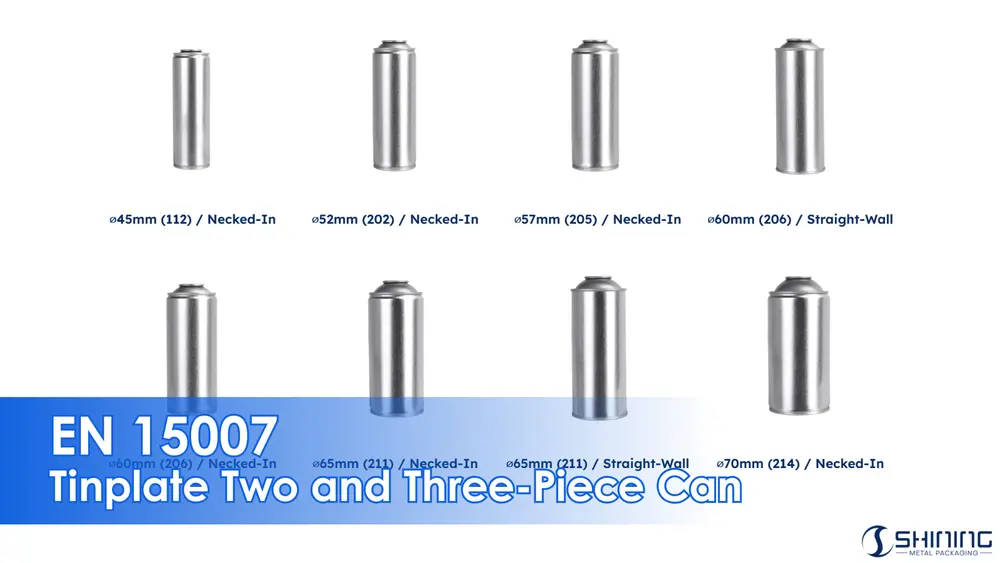
2.1 Dimensions for Necked-In Containers
For necked-in cans, the dimensions provided below ensure the integrity of the can structure while allowing for optimal valve cup clinching.

1 aperture (in accordance with EN 14847)
2.2 Dimensions for Straight-Sided Containers

1 aperture (in accordance with EN 14847)
Straight-sided containers maintain consistent diameters along their height. Below are the standard dimensions for these types of cans:
Table 1 — Nominal brimful capacities and dimensions for Tinplate aerosol containers
| Brimful capacitya C2 (ml) |
Nominal fill V (ml) |
Body D (mm) |
Top end DN1 (mm) |
Bottom end DN2 (mm) |
H1 (mm) |
H2 (mm) |
H3 (mm) |
D1 (mm) |
C (mm) |
H5 (mm) |
D2 (mm) |
|||
|---|---|---|---|---|---|---|---|---|---|---|---|---|---|---|
| nom | min | max | liquefied gasb
/ compressed gasc |
|||||||||||
| 140 | 134 | 146 | 100 | 75 | 45 | 41 | 42 | 96 | 5.6 | 101.6 | 43.6 | 2.9 | 5.3 | 45.2 |
| 175 | 169 | 181 | 125 | 100 | 45 | 41 | 42 | 118 | 5.6 | 123.6 | 43.6 | 2.9 | 5.3 | 45.2 |
| 210 | 204 | 216 | 150 | 125 | 45 | 41 | 42 | 140 | 5.6 | 145.6 | 43.6 | 2.9 | 5.3 | 45.2 |
| 240 | 233 | 247 | 175 | 135 | 45 | 41 | 42 | 158 | 5.6 | 163.6 | 43.6 | 2.9 | 5.3 | 45.2 |
| 270 | 262 | 278 | 200 | 150 | 45 | 41 | 42 | 178 | 5.6 | 183.6 | 43.6 | 2.9 | 5.3 | 45.2 |
| 210 | 204 | 216 | 150 | 125 | 49 | 45 | 46 / 47d | 119 | 7.0 | 126.0 | 47.8 | 2.9 | 5.5 | 49.3 |
| 270 | 262 | 278 | 200 | 150 | 49 | 45 | 46 / 47d | 151 | 7.0 | 158.0 | 47.8 | 2.9 | 5.5 | 49.3 |
| 305 | 297 | 313 | 225 | 175 | 49 | 45 | 46 / 47d | 169 | 7.0 | 176.0 | 47.8 | 2.9 | 5.5 | 49.3 |
| 335 | 325 | 345 | 250 | 200 | 49 | 45 | 46 / 47d | 185 | 7.0 | 192.0 | 47.8 | 2.9 | 5.5 | 49.3 |
| 405 | 393 | 417 | 300 | 250 | 49 | 45 | 46 / 47d | 222 | 7.0 | 229.0 | 47.8 | 2.9 | 5.5 | 49.3 |
| 140 | 134 | 146 | 100 | 75 | 52 | 48 | 50 | 72 | 8.0 | 80.0 | 50.7 | 3.2 | 5.6 | 52.7 |
| 175 | 169 | 181 | 125 | 100 | 52 | 48 | 50 | 88 | 8.0 | 96.0 | 50.7 | 3.2 | 5.6 | 52.7 |
| 210 | 204 | 216 | 150 | 125 | 52 | 48 | 50 | 105 | 8.0 | 113.0 | 50.7 | 3.2 | 5.6 | 52.7 |
| 270 | 262 | 278 | 200 | 150 | 52 | 48 | 50 | 132 | 8.0 | 140.0 | 50.7 | 3.2 | 5.6 | 52.7 |
| 335 | 325 | 345 | 250 | 200 | 52 | 48 | 50 | 161 | 8.0 | 169.0 | 50.7 | 3.2 | 5.6 | 52.7 |
| 405 | 393 | 417 | 300 | 250 | 52 | 48 | 50 | 195 | 8.0 | 203.0 | 50.7 | 3.2 | 5.6 | 52.7 |
| 520 | 507 | 533 | 400 | 300 | 52 | 48 | 50 | 244 | 8.0 | 252.0 | 50.7 | 3.2 | 5.6 | 52.7 |
| 270 | 262 | 278 | 200 | 150 | 57 | 52 | 54 | 110 | 9.5 | 119.5 | 55.5 | 3.3 | 6.0 | 57.6 |
| 335 | 325 | 345 | 250 | 200 | 57 | 52 | 54 | 136 | 9.5 | 145.5 | 55.5 | 3.3 | 6.0 | 57.6 |
| 405 | 393 | 417 | 300 | 250 | 57 | 52 | 54 | 164 | 9.5 | 173.5 | 55.5 | 3.3 | 6.0 | 57.6 |
| 520 | 507 | 533 | 400 | 300 | 57 | 52 | 54 | 207 | 9.5 | 216.5 | 55.5 | 3.3 | 6.0 | 57.6 |
| 650 | 637 | 663 | 500 | 400 | 57 | 52 | 54 | 257 | 9.5 | 266.5 | 55.5 | 3.3 | 6.0 | 57.6 |
| 405 | 393 | 417 | 300 | 250 | 65 | 60 | 63 | 122 | 13.5 | 135.5 | 63.2 | 3.3 | 6.3 | 65.9 |
| 520 | 507 | 533 | 400 | 300 | 65 | 60 | 63 | 157 | 13.5 | 170.5 | 63.2 | 3.3 | 6.3 | 65.9 |
| 650 | 637 | 663 | 500 | 400 | 65 | 60 | 63 | 195 | 13.5 | 208.5 | 63.2 | 3.3 | 6.3 | 65.9 |
| 800 | 784 | 816 | 600 | 500 | 65 | 60 | 63 | 240 | 13.5 | 253.5 | 63.2 | 3.3 | 6.3 | 65.9 |
| 1000 | 980 | 1020 | 750 | 600 | 65 | 60 | 63 | 300 | 13.5 | 313.5 | 63.2 | 3.3 | 6.3 | 65.9 |
a The minimum and maximum values have been calculated in accordance with EN ISO 90-3.
b Products propelled by liquefied gas.
c Products propelled by compressed gases alone or by mixtures with nitrous oxide or carbon dioxide when the Bunsen coefficient is ≤ 1.2.
d Depending on companies.
3.Designation of Aerosol Containers
Aerosol cans should be designated according to the following:
- Nominal brimful capacity (C2), in millilitres.
- Characteristic diameters (D) in millimetres.
- Nominal height (H1) in millimetres.
For necked-in cans with different top and bottom diameters, the designation should also include the diameters for both ends (e.g., C2/D/DN1/DN2/H1).
4.Measurement Methods
4.1 Measurement of Aperture
The aperture should conform to the dimensions specified in EN 14847, ensuring the proper valve cup fitment.
4.2 Measuring Diameters and Heights
Use standard measuring instruments like calipers and gauges to capture the dimensions at specified points, ensuring compliance with the tolerances listed in the tables above.
Download the Standard PDF
This document presents EN 15007, specifying dimensional requirements for two-piece and three-piece tinplate aerosol containers. It defines nominal brimful capacities, key diameters, and height dimensions for necked-in and straight-sided cans, supporting standardized design, manufacturing control, and dimensional verification across aerosol packaging applications.
Frequently Asked Questions (FAQ)
EN 15007 defines the overall dimensions of tinplate two- and three-piece aerosol cans. It must be used together with EN 14847 for aperture geometry and EN 14848 for valve cup dimensions to ensure sealing and filling compatibility.
Necked-in designs reduce the valve diameter while maintaining the required internal volume. This improves ergonomics, reduces material usage at the top end, and ensures compatibility with standard 25.4 mm valve systems.
Not without adjustment. Differences in height, center of gravity, and top-end geometry affect filling head alignment and clinching behavior. Filling lines must be validated before switching between these container types.
Custom designs are possible, but deviations from EN 15007 must still respect functional limits for sealing and filling. Non-compliant dimensions often reduce interchangeability and increase process variability.
EN 15007 is not legally mandatory, but it represents widely accepted industry practice. Using this standard significantly reduces the risk of dimensional mismatch between cans, valves, and filling equipment.
