Standard Overview
FEA 222 is an industry guideline issued by the European Aerosol Federation (FEA), describing how to achieve optimum clinch conditions for metal aerosol containers with a 25.4 mm opening.
Unlike dimensional standards, FEA 222 focuses on process optimisation: how container, valve, tooling and machine settings interact to produce a tight and durable seal.
1. Standards Referenced by FEA 222
FEA 222 builds directly on the following standards:
- EN 14847 – Tinplate container aperture dimensions
- EN 14848 – Valve cup dimensions
- EN 15006 – Aluminium container aperture dimensions
- EN 15010 – Aluminium clinch-related tolerances
- EN 14850 – Measurement of contact height
- FEA 216 – Bearing surfaces of clinching jaws
2. Key Factors Influencing Clinch Performance
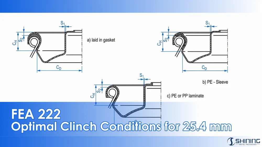
2.1 Container Contact Height (h)
Contact height is the reference dimension between the top of the container aperture and the point of hard contact of the clinching jaws.
| Container Type | Typical Contact Height Range |
|---|---|
| Tinplate containers | 3.85 – 4.15 mm |
| Aluminium containers | 4.05 – 4.45 mm |

2.2 Valve Cup and Sealing Compound

| Parameter | Typical Range | Impact on Clinch |
|---|---|---|
| Cup wall thickness (S1) | 0.24 – 0.44 mm | Defines clinch diameter and stiffness |
| Sealing compound thickness (S2) | 0.2 – 1.3 mm | Controls gasket compression |
| Compression factor (f1) | 0 – 0.5 | Defines effective gasket thickness |
3. Clinch Height (CH) – Calculation Logic
FEA 222 defines a calculation method for setting the target clinch height:
CH = h + S1 + S2 × (1 − f1)
The recommended tolerance for clinch height is ± 0.1 mm.4. Clinch Diameter (CD) – Adjustment Principle
Clinch diameter must be adjusted according to valve cup wall thickness:
CD = Di + 2 × (Ci − S1)
- Di = 25.4 mm (internal aperture diameter)
- Ci = 1.15 mm (instrument constant)
| S1 (mm) | Recommended CD (mm) |
|---|---|
| 0.24 | 27.22 |
| 0.30 | 27.10 |
| 0.34 | 27.02 |
| 0.40 | 26.90 |
| 0.44 | 26.82 |
5. Head Load and Machine Settings
FEA 222 recommends a clinch head load typically between 60 and 95 daN, depending on gasket type and internal pressure.
6. Testing Procedures for Seal Performance
6.1 Setting Up Prior to and During Filling
Various tests ensure the integrity of the clinch seal:
- Embedded Cup Cross Sectioning: This test involves cutting a section of the clinched valve to observe the compression of the outer gasket and deformation of the bead.
- Waterbath Testing: Used to check the mechanical strength and sealing performance of the finished aerosol during production (see FEA 606 for detailed testing methods).
6.2 Quick Test Methods

These quick tests check for leakage:
- Cold Water Immersion Test: The internal pressure of the filled container is increased, and the can is assessed for leakage.
- Warm Water Immersion Test: Containers are immersed in warm water (~40°C) for 15 minutes and checked for leakage visually.

6.3 Long-Term Tests
To ensure long-term sealing reliability, the following tests are conducted:
- Eudiometer Tube Test: Quantitatively measures gas seepage between the valve cup and container bead.
- Weight Loss Determination: Used to measure long-term preservation and gas loss.
- Temperature Cycling Test: Containers are subjected to temperature changes between 40°C and 0°C to test seal integrity under varying environmental conditions.

Download the Standard PDF
This document provides FEA 222, offering practical guidelines for achieving optimum clinch conditions on metal aerosol containers with a 25.4 mm opening. It addresses critical parameters, calculation methods, tooling considerations, and test procedures to ensure reliable sealing performance.
FAQ – Engineering & QA
FEA 222 is not legally mandatory, but it represents consolidated industry best practice. In many European filling plants, it is treated as a de facto reference when setting up or auditing clinch processes. Ignoring it often leads to recurring leakage issues that are difficult to trace.
No. Clinch height depends on valve cup wall thickness, gasket type, and gasket compression behaviour. Using a single clinch height for different valves may appear acceptable initially but often causes long-term seal relaxation.
This typically occurs when gasket compression is uneven or insufficient at the time of clinching. Over time, elastic recovery of the gasket and metal components reduces sealing pressure, leading to delayed leakage.
No. Head load alone cannot ensure a reliable seal if the clinch geometry is incorrect. The clinch profile governs how the applied force is distributed around the gasket, directly influencing compression uniformity, sealing integrity, and long-term performance.
No. Water bath testing detects immediate leaks caused by gross defects. It does not predict long-term sealing performance under storage, temperature cycling, or pressure variation.
Generally no. Aluminium and tinplate deform differently under load and require different contact heights and clinch diameters. Applying the same settings often results in over-compression or insufficient sealing on one of the materials.
Yes, especially for high-speed or multi-supplier filling lines. Referencing FEA 222 helps align expectations between can suppliers, valve suppliers, and fillers.
The most common mistake is relying on nominal dimensions rather than calculated and verified clinch parameters. This approach may appear acceptable during setup but frequently results in unstable sealing performance under actual production conditions.
